// Documenti disponibili n: 46.254
// Documenti scaricati n: 35.983.232
La norma, con esempi estratti in allegato, fornisce indicazioni per Sistemi di Orientamento per le Vie di Esodo e descrive i principi che regolano la progettazione e l'applicazione delle componenti visive utilizzate per creare un SWGS (Safety Way Guidance System).
ISO 16069:2017 Simboli grafici - Segnaletica di sicurezza - Sistemi di Orientamento per le Vie di Esodo e descrive i principi che regolano la progettazione e l'applicazione delle componenti visive utilizzate per creare un Sistema di Orientamento per le Vie di Esodo (SWGS - Safety Way Guidance System).
ISO 16069:2017 contiene principi generali validi sia per componenti elettrici che per componenti fosforescenti.
Informazioni speciali relative al tipo di componente sono fornite per aiutare a definire l'ambiente di utilizzo, la scelta del materiale, il layout, l'installazione e la manutenzione di SWGS. ISO 16069:2017 non copre la valutazione del rischio.
Le applicazioni con rischi diversi per gli occupanti richiedono in genere layout e tipi diversi di SWGS.
L'applicazione specifica e l'esatto progetto definitivo di SWGS sono affidati alle persone responsabili di questo compito.
ISO 16069:2017 non include inoltre le considerazioni speciali su possibili componenti tattili o udibili di SWGS, né include i requisiti per i componenti montati in alto dell'illuminazione della via di fuga di emergenza, in particolare la progettazione e l'applicazione dell'illuminazione della via di fuga di emergenza.
ISO 16069:2017 è previsto, per collaborazione e coordinamento, per essere utilizzato da tutti gli altri comitati tecnici all'interno di ISO e IEC incaricati di sviluppare SWGS per le loro esigenze specifiche.
ISO 16069: 2017 non deve essere utilizzato per le navi che rientrano nei regolamenti dell'Organizzazione marittima internazionale (IMO).
La necessità di sistemi di orientamento di percorsi di uscita universali negli edifici per condurre le persone alla sicurezza è stata considerata da ISO / TC 145 nel 1997 come una delle applicazioni più critiche per la segnaletica standardizzata.
Per 6 anni un comitato multidisciplinare di esperti mondiali nei sistemi di evacuazione e simboli grafici si è riunito diverse volte l'anno per sviluppare la ISO 16069.
Il risultato, pubblicato nel 2003, è uno standard che stabilisce i principi di base per la progettazione di sistemi di marcatura di percorsi di uscita per edifici.
I suoi componenti e concetti ben definiti includono:
- Segnali di direzione direzionale
- Linee guida continue
- Segni di passaggio
- Marcature di corrimano
- Segni di porte e segni perimetrali
- Posizionamento posizione alta, intermedia e bassa
- Criteri di prestazione della luminanza per materiali fotoluminescenti
La segnaletica definita nella ISO 16069 utilizza i simboli della ISO 7010 e i criteri di progettazione della segnaletica presentati in ISO 3864. Una serie di figure informative è mostrata nella ISO 16069 per illustrare come vengono utilizzati i concetti dello standard.
La segnaletica d’esodo deve essere adeguata alla complessità dell’attività e consentire l’orientamento degli occupanti (wayfinding) a tal fine:
- Devono essere installate in ogni piano dell’attività apposite planimetrie in cui sia indicata la posizione del lettore ed il layout del sistema d’esodo.
- Possono essere applicate le indicazioni contenute nelle ISO 23601 e ISO 16069.
(*) Attenzione. Documento elaborato su norma Ed. 2004, controllare su Ed. in vigore 2017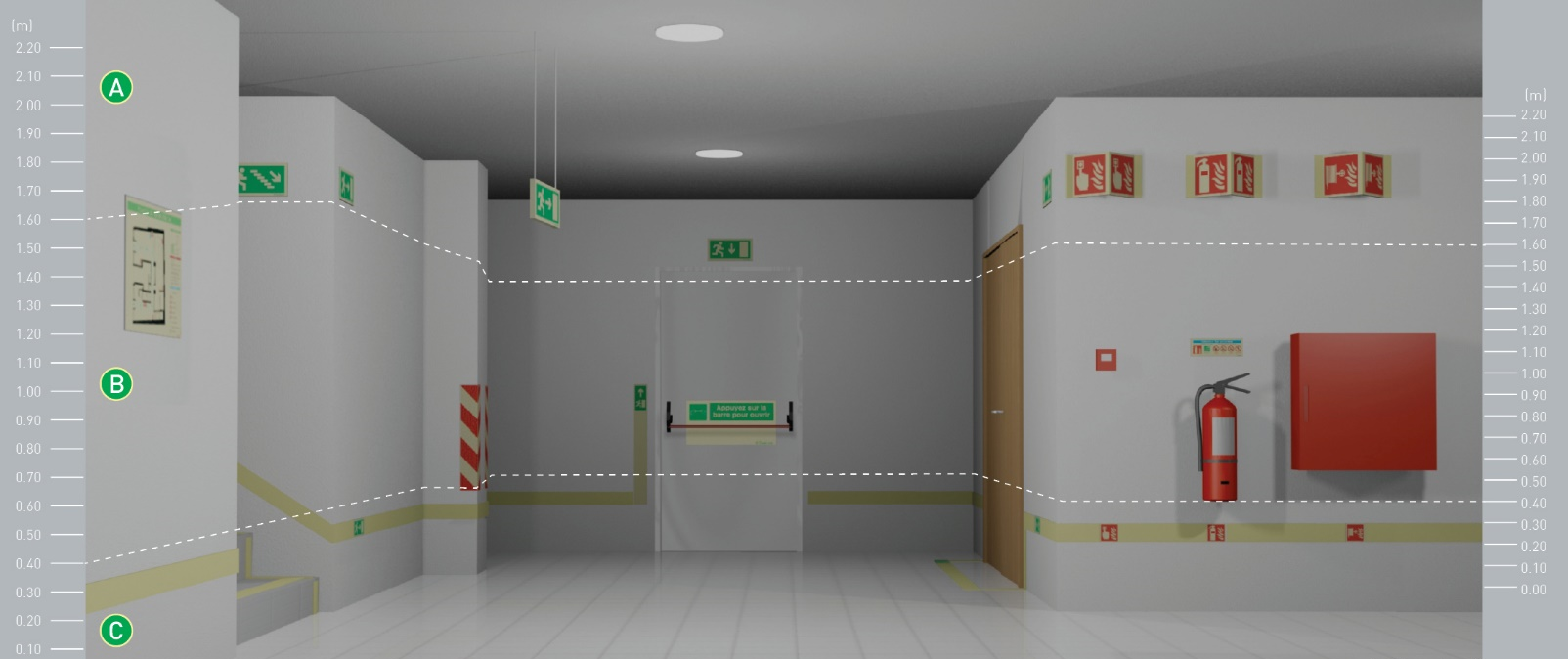
Annex A - (informative) Examples of SWGS layouts
The example layouts in this annex are provided to illustrate an assembly of components that represents good SWGS principles.
The examples given in this annex should not be assumed to be exhaustive. Other layouts using different components may be used where determined necessary by risk assessment or the particular design criteria of the escape route.
The different components of SWGS illustrated in the examples are partly described only for the purpose of assisting comprehension of the drawings.
Figure A.1 Example layout of a T-junction leading into straight corridor no wider than 2 m and no longer than 10 m
Figure A.2 Example layout of a T-junction leading into a straight corridor no wider than 2 m with illumination to highlight the door and the T-junction
Figure A.3 Example layout of a corridor wider than 2 m with low mounted guidance lines on both sides
Figure A.4 Example layout of a T-junction leading into a straight corridor wider than 2 m with an adjoining door (demarked by a floor guidance line)
Figure A.5 Example layout of a T-junction leading into a straight corridor wider than 2 m with focused illumination on T-junction and door
Figure A.6 Example layout of a T-junction leading into a straight corridor wider than 2 m with adjoining door using floor guidance lines and integrated directional indicators
Figure A.7 Example layout of a T-junction leading into a straight corridor (with more than one door) showing continuity of signing
Figure A.8 Example layout of a T-junction leading into a straight corridor less than 2 m with focused illumination at the doors, provided by high-mounted single-sided transilluminated safety signs
Figure A.9 Example layout of a building feature marking and directional marking through doors
Figure A.10 Example layout of an alternative building feature marking and full frame door marking
Figure A.11 Example layout of markings for a dead end corridor no wider than 2 m
Figure A.12 Example layout of an intersection marked by floor guidance lines
Figure A.13 Example layout of an intersection illustrating floor guidance lines with integrated directional indicators
Figure A.14 Example layout of an intersection with a wall-mounted guidance line
Figure A.15 Example layout of an open space illustrating floor guidance lines with integrated directional indicators
Figure A.16 Example layout of an open space with intersection and floor guidance line with intersection
Figure A.17 Example layout of a collection of different marking of stairs and handrails
Figure A.18 Example layout of stairs where the stair treads are illuminated with luminaires
Figure A.19 Example layout of stairs where the treads are illuminated by low mounted luminaires on the wall
Figure A.20 Example layout of signing and marking of ramp (change of level)
Figure A.21 Example layout of signing and marking of ramp (change of level)
Excursus
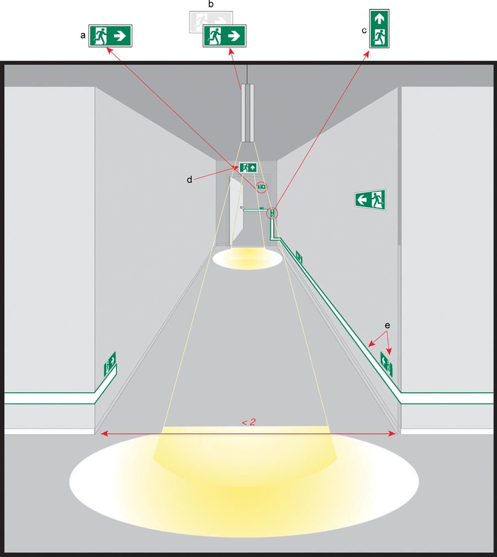
Figure A.2 Example layout of a T-junction leading into a straight corridor no wider than 2 m with illumination to highlight the door and the T-junction (Dimensions in metres)
This illustration depicts an example of components used to convey one of several possible layouts of a safety way guidance system for a typical detail of the escape route.
a High-mounted single-sided transilluminated safety sign.
b High-mounted double-sided transilluminated safety sign (suspended or at the ceiling) with illumination to highlight the T-junction.
c Transilluminated indicator at height of the door handle.
d High-mounted single-sided transilluminated safety sign with illumination to highlight the door.
e Guidance line with directional indicator.
....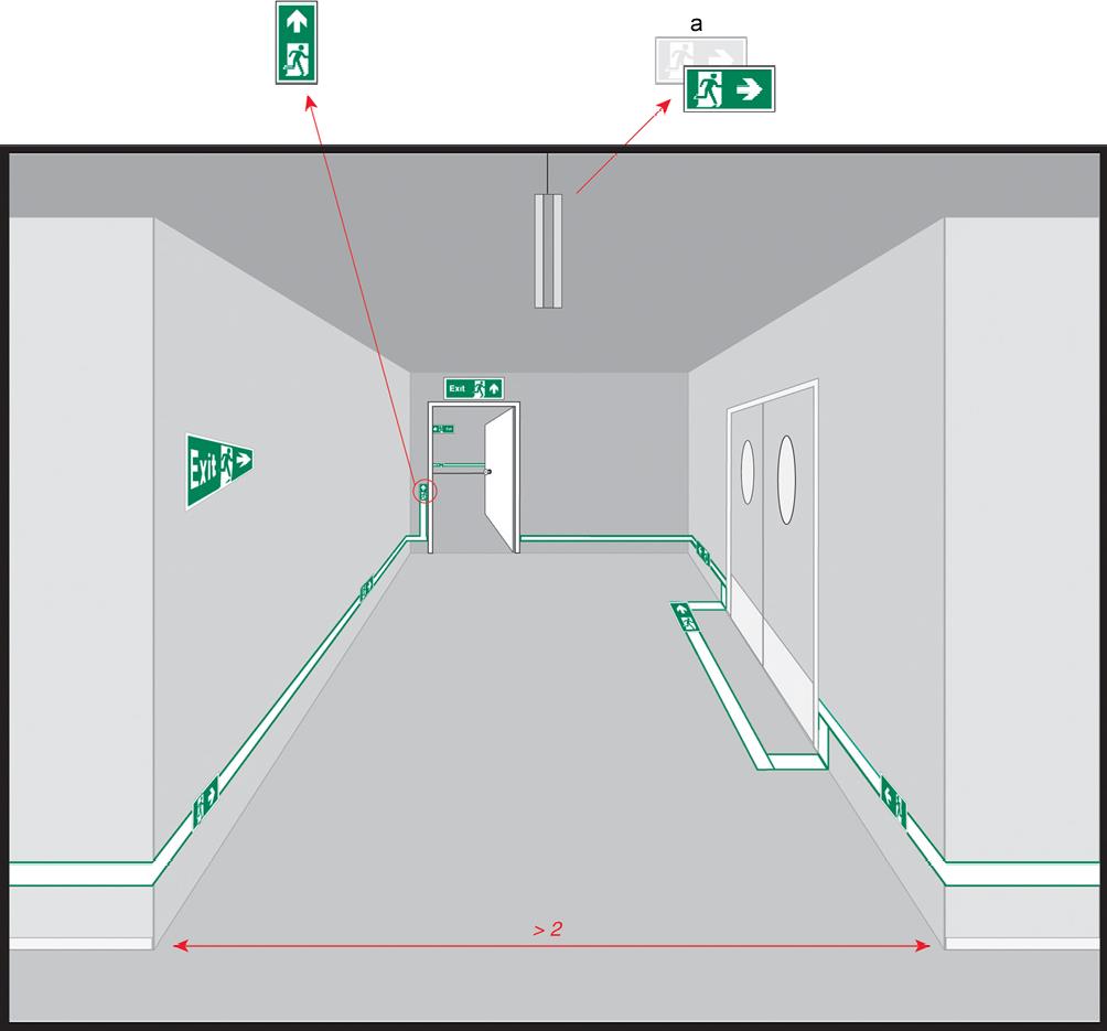
Figure A.4 Example layout of a T-junction leading into a straight corridor wider than 2 m with an adjoining door (demarked by a floor guidance line) (Dimensions in metres)
This illustration depicts an example of components used to convey one of several possible layouts of a safety way guidance system for a typical detail of the escape route.
a High-mounted double-sided safety sign (suspended from the ceiling).
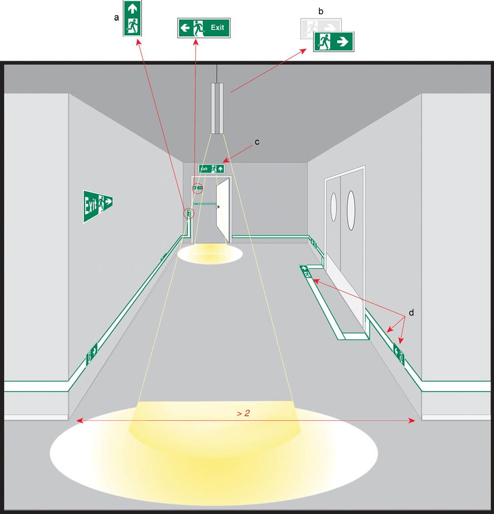
Figure A.5 Example layout of a T-junction leading into a straight corridor wider than 2 m with focused illumination on T-junction and door (Dimensions in metres)
This illustration depicts an example of components used to convey one of several possible layouts of a safety way guidance system for a typical detail of the escape route.
a Transilluminated indicator at height of the door handle.
b High-mounted double-sided transilluminated safety sign (suspended or at the ceiling) with illumination to highlight the T-junction.
c High-mounted single-sided transilluminated safety sign with illumination to highlight the door.
d Guidance line with integrated directional indicator.
...
Figure A.10 Example layout of an alternative building feature marking and full frame door marking
This illustration depicts an example of components used to convey one of several possible layouts of a safety way guidance system for a typical detail of the escape route.
Figure A.13 Example layout of an intersection illustrating floor guidance lines with integrated directional indicators
This illustration depicts an example of components used to convey one of several possible layouts of a safety way guidance system for a typical detail of the escape route.
a High-mounted double-sided safety sign (suspended from the ceiling).
...
Figure A.18 Example layout of stairs where the stair treads are illuminated with luminaires
This illustration depicts an example of components used to convey one of several possible layouts of a safety way guidance system for a typical detail of the escape route.
a Luminaires to illuminate the tread of stairs.
b Handrail may be highlighted.
...
Figure A.21 Example layout of signing and marking of ramp (change of level)
This illustration depicts an example of components used to convey one of several possible layouts of a safety way guidance system for a typical detail of the escape route.
a High-mounted single-sided transilluminated safety sign with illumination to mark the ramp.
b High-mounted single-sided transilluminated safety sign (suspended or at the ceiling) with illumination down lighting from the escape route sign luminaire to highlight the door and the end of the ramp.
...add more
Fonte: 16069:2004 Graphical symbols - Safety signs - safety way guidance systems (SWGS)
(Controllare su norma in vigore Ed. 2017)
Certifico Srl - IT | Rev. 00 2019
©Copia autorizzata Abbonati
http://store.uni.com/catalogo/index.php/iso-16069-2017.html
Collegati

Infortunio con la macchina "Calandra Bridge". Il dispositivo di sicurezza che provoca l'arresto dei rulli compressori ma non anche la contemporanea ...

Nota dipvvf. DCPREV.REGISTRO UFFICIALE.U.0009105.08-07-2020
In riscontro al quesito inviato, relativo alla possibilità di installazione di ...

ID 20596 | 16.10.2023 / In allegato
Malprof, Invecchiamento della popolazione attiva: una lettura del fenomeno a partire dai dati del sistema Malprof
L’...
Testata editoriale iscritta al n. 22/2024 del registro periodici della cancelleria del Tribunale di Perugia in data 19.11.2024