ISO/TS 19837:2018 - Trapped Key Interlocking Devices
| Appunti Direttiva macchine | ||
| 07 Luglio 2025 | ||
 |
||
| Salve Visitatore | ||
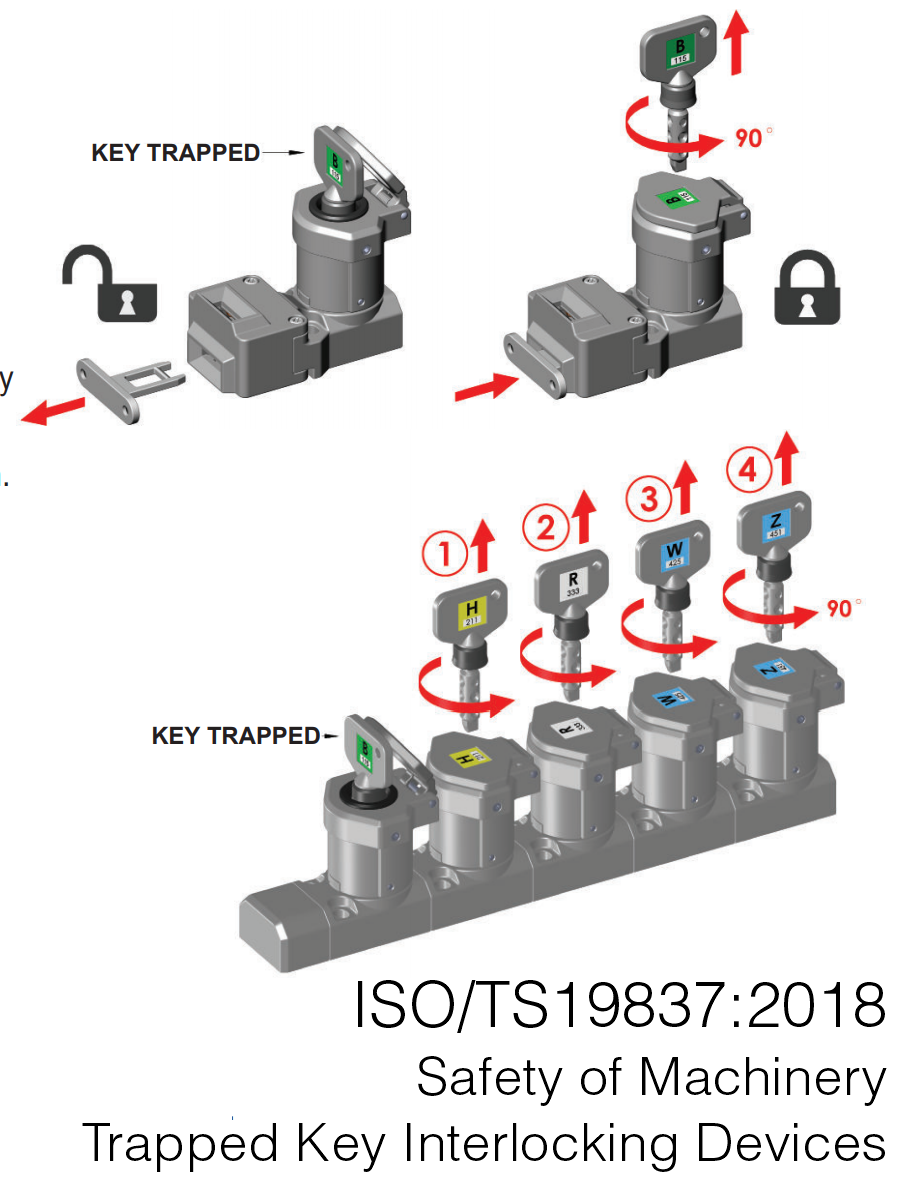
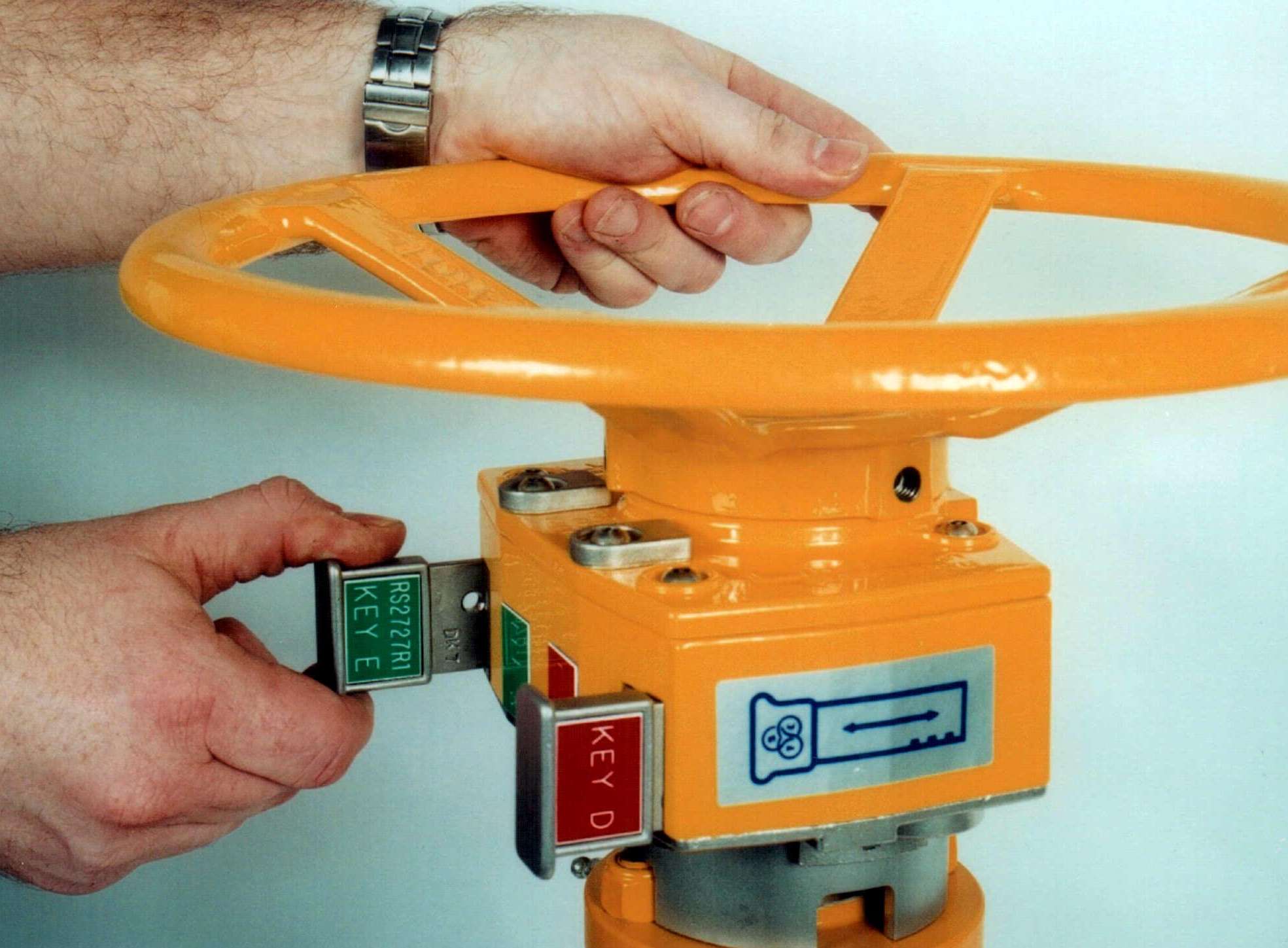
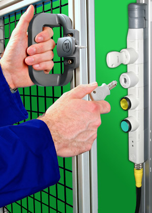
ISO/TS 19837:2018 - Trapped Key Interlocking Devices ID 7848 | 26.02.2019 Preview ISO/TS 19837:2018 and Document in attachment ISO/TS 19837:2018 - Safety of Machinery – Trapped Key Interlocking Devices – Principles for design, selection and configuration’ is the first international ISO document devoted specifically to trapped key interlocking and answers many of the questions that have arisen relating to performance levels, key coding, and power interlocking. It is a significant step forward which will provide more choice for users of interlock devices and systems. Trapped Key Interlocking has its roots in the rail and power distribution industries where sequential control was, and still is, critical to safe, continuous operation. In the 1960s trapped key interlocking was gradually utilised by the manufacturing sector, where isolating machinery before gaining access, was the requirement. Machinery with multiple energy sources and access points can be easily safeguarded using trapped key interlocks. Fortress Interlocks has developed specialised products over the years which can isolate air and hydraulic supplies as well as electrical power in sequence before allowing access points to be opened. When ‘ISO14119:2013 Safety of Machinery – Interlocking device associated with guards, Principles for design and selection’ was published, trapped key interlocking had become no more than an annex, even the scope was clear that it did not provide all the specific requirements for trapped key systems. In many respects ISO14119:2013 served to confuse users and potential users familiar with decades of trapped key interlocks installations. ISO/TS 19837:2018, three years in the making, is a welcome addition to the existing suite of machinery safety standards. Perhaps the most critical question addressed is where mechanical or hybrid mechanical/electrical systems sit in relation to performance levels introduced in ISO 13849. Power Interlocking is now more properly referred to as “Isolation control through direct mechanical action” and falls within the Safety Related Part of The Control System. This coupled with the section “Validating performance level” makes evaluating performance levels for trapped key systems much clearer. The difference between actuators and keys is cleared up, following the confusion created in ISO14119:2013, and both are addressed in the “Terms and definitions” and “Symbols and abbreviated terms” sections. The need for a schematic detailing the trapped key system operation and establishing key coding appears under “Key Transfer Plan” and will provide users with an excellent tool in the system design phase as well as a documented system layout after installation. Key coding and management is also addressed extensively. A much-needed standardisation of symbols to represent trapped key interlocks will make it easier for customers to understand schematics, and the excellent pictorial examples throughout the document are useful for those building a trapped key interlock system. The publication of ISO/TS 19837 will help to keep trapped key interlocking at the forefront of machine safety in the future, it is very much welcomed by Fortress. We have worked hard to ensure Fortress products meet the most stringent safety standards and our trapped key interlocks are no exception. It is good to finally have a document that helps our customers understand better how trapped key interlocks fit within the international machinery safety standards. For those seeking help our experienced team of sales engineers is able to provide support and guidance.” Trapped Key Interlocking Many machine designers think of interlocks as exclusively electrical devices; a switch is attached to a movable mechanical guard, and the switch is connected to the control system. Trapped Key Interlocking is a way to interlock guards that is equally effective, and often more appropriate in severe environmental conditions. Trapped Key Interlocking [1] I’ve provided some useful definitions and links to additional reading at the end of the article. Trapped Key interlocking uses mechanical interlocking devices to ensure that guards remain closed unless the machinery is stopped.
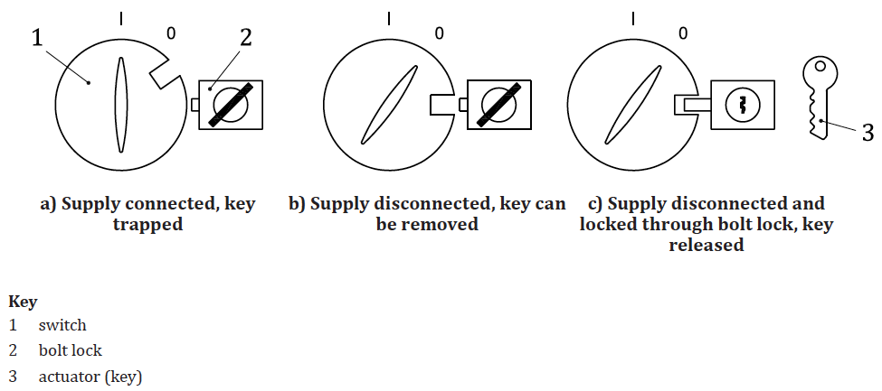
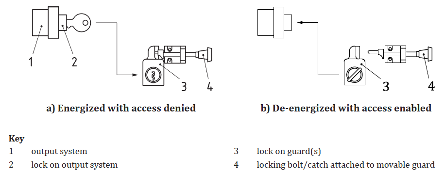
Another significant benefit of trapped key interlocking is the ability of the interlocking devices to withstand infrequent use. Electrical interlocking devices can fail from lack of use, and these failures might not be detected by the automatic diagnostics provided by the safety relay, controller or safety PLC ISO 14119 [1, 8.2] discusses the need to physically test the operation of rarely used interlocks to ensure that the diagnostics can check the function of the interlocking device Trapped Key Interlocking, also called key transfer interlocking, is a system of mechanical locks installed on gates, valves, etc. The system relies on the transfer of keys from a control device to a lock that controls access into the danger zone of the machine. The diagram below, [1, Fig. B.3], shows the simplest form, where a locking device is used to prevent the energization of a machine by locking the supply disconnecting device. The simplest form of a trapped key interlock [1, Fig. B.3] Guards can also be interlocked in this way, [1, Fig. B.5]. In this case, the locking device is used to shut off power to the hazardous motions, and the key is removed from the control device. The key is required to open the machine guard, where the key remains trapped until the guard is closed and locked. The key can then be returned to the control device, and power restored to the machine to allow it to run. Simple trapped-key interlock with one guard [1, Fig. B.5]
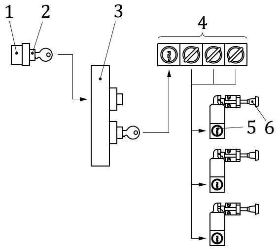
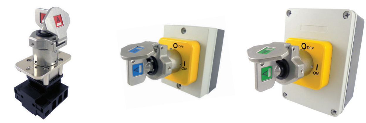
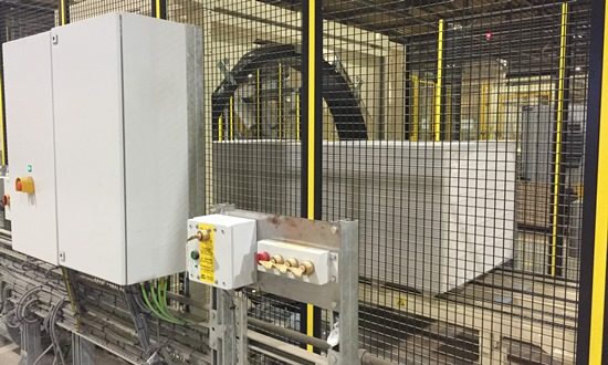
The essential feature of the system is that the removable key is trapped either in the guard lock or the switch lock. The lock on the guard is arranged so that the key can only be released when the guard has been closed and locked. The key can then be transferred from the guard to the switch lock. Turning the key to the “ON” or “RUN” positions traps the key so that it cannot be removed (see [1, Fig. B.3] and [1, Fig. B.5]). The operating principle is: 1. Turn the control key from the run position to the stop position and remove it from the control device lock. Complex Access Control The approach described previously works well for simple, single-point interlocking, but there are many more complex situations where mechanical interlocks could be used. An additional component, called a “key transfer block,” is used to provide an intermediate location. Defined sequences of operations, time delays, and multiple access points can be controlled using this approach. Trapped Key transfer block [2] In a complex interlocking system, the control key is transferred from the control switch lock (2 in [1, Fig. B.6] below) to an intermediate key-transfer block (3 in [1, Fig. B.6] below). Turning the control key in this block releases one or more keys that then can be used to release access keys in a secondary transfer block (4 in [1, Fig. B.6] below). Individual guards can then be unlocked, and safe access permitted. Complex interlocking using trapped keys. [1, Fig. B.6] This same approach can be used at the guards, where another key can be released when the guard is unlocked. This key can then be taken inside the safeguarded space and used, for example, to release a robot teach pendant, or to enable robot teaching at reduced, “safe” speed. Diagnostics Since the field interlocks don’t have any electrical sensing in most systems, it is possible to have one of the field interlocking devices fail and have the failure go unnoticed or ignored. This can be mitigated in at least two ways: 1. Combine the mechanical interlock with an electrical interlocking device. You will lose some of the other advantages to the system by doing this, but if increased diagnostics are needed, an electrical interlock can help meet that requirement. 2. Combine the field interlocking device with either an electrical disconnecting means or a fluidic system supply valve so that power to the area is cut off when the guard is opened. Additional diagnostics can be added to these measures as well, allowing a designer to meet high diagnostic requirements. Final Thoughts Trapped key interlocking systems have many advantages, particularly in challenging environmental conditions, and where low-frequency of access increases the risk of undetected faults resulting in the loss of the safety function when the interlock fails. Trapped key systems have many other advantages and relatively few disadvantages, but are not used as frequently as electrical interlocking systems because safety system design is often done by controls designers who are more likely to seek an electrical or electrical/software solution before considering “old-school” mechanical solutions. The next time you are designing an interlocking safety function for a machine, consider using a trapped key system. Definitions All definitions from [1] unless otherwise noted. interlocking device interlocking guard guard locking device interlocking guard with guard locking tool power interlocking 2. interlocking which directly interrupts the energy supply to the machine actuators or disconnects moving parts from the machine actuators ISO/TS 19837:2018(en), 3.15 trapped key interlocking system trapped key interlocking device access lock personnel key control interlocking References [1] Safety of machinery - Interlocking devices associated with guards - Principles for design and selection. ISO 14119:2013. https://www.iso.org/standard/66335.html
|
||
 |
||
|
sono siti di: Se vuoi cancellarti dall'invio della newsletter oppure effettua il login al sito ed entra nella Tua Area Riservata, in “Modifica dati” agisci con la spunta sul box di selezione “newsletter”. L'Elenco completo di tutte le ns newsletter è qui: Archivio newsletter |
||
  |
||
| Certifico Srl 2000-2019 | VAT IT02442650541 | ||


