UNI EN ISO 16090-1 Sicurezza Centri di lavoro, fresatrici / Taglio a freddo metalli - P.1 Suddivisione in gruppi
| Appunti Marcatura CE | ||
| 13 Luglio 2025 | ||
| Salve Visitatore | ||
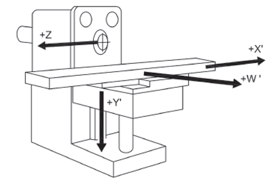
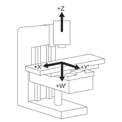
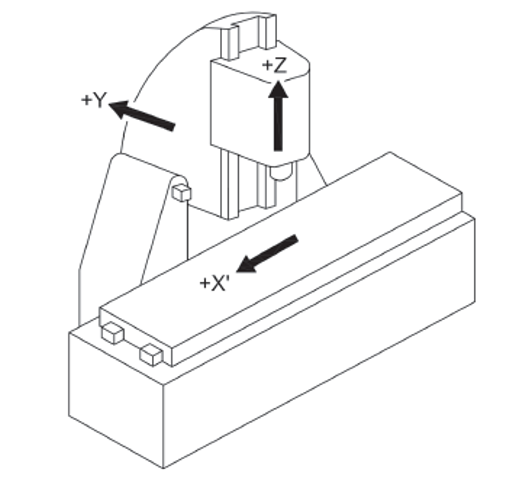
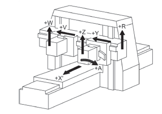
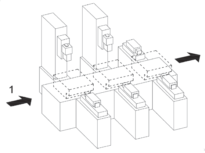
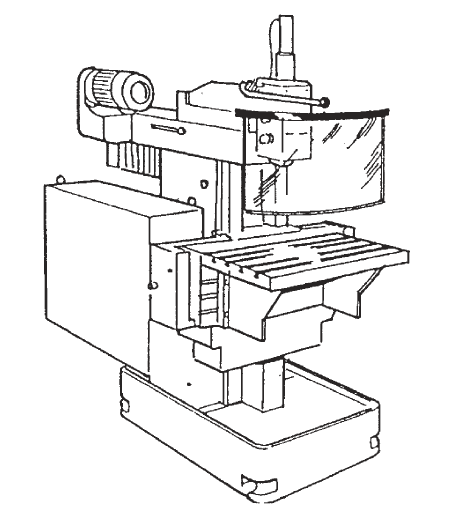
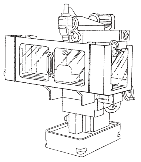
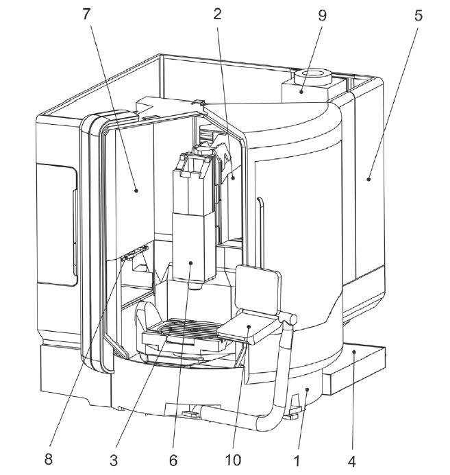
UNI EN ISO 16090-1 Sicurezza Centri lavoro, fresatrici taglio metalli ID 17927 | 25.10.2022 / Documento in allegato - Licenza ISO Certifico Srl La UNI EN ISO 16090-1:2019 (tipo C ai sensi della EN ISO 12100), specifica i requisiti tecnici di sicurezza e le misure di protezione per la progettazione, la costruzione e la fornitura delle macchine utensili utilizzate per il taglio a freddo di metalli e materiali non combustibili (alesatrici, fresatrici, centri di lavoro, macchine transfer e macchine speciali. La norma, alla data, non è armonizzata per la Direttiva macchine 2006/42/CE. Documento d'interesse per i Costruttori (Direttiva macchine 2006/42/CE) e Utilizzatori (D.Lgs. 81.2008). Doc. 1. Suddivisione in gruppi UNI EN ISO 16090-1:2019 Sicurezza delle macchine utensili - Centri di lavoro, fresatrici, macchine transfer - Parte 1: Requisiti di sicurezza La norma specifica i requisiti tecnici di sicurezza e le misure di protezione per la progettazione, la costruzione e la fornitura (inclusi l'installazione e lo smantellamento, le modalità di trasporto e manutenzione) delle fresatrici fisse, incluse le macchine in grado di eseguire operazioni di alesatura, centri di lavoro e macchine transfer che sono destinate a tagliare a freddo metalli e altri materiali non combustibili ad eccezione del legno o materiali con caratteristiche fisiche simili a quelle del legno come definito nella norma UNI EN ISO 19085-1, e vetro, pietra e materiali lapidei agglomerati come definiti nella UNI EN 14618. La norma si applica alle seguenti macchine: a) alesatrici e fresatrici a comando manuale senza controllo numerico; La norma tratta tutti i pericoli significativi nonché le situazioni pericolose e gli eventi pericolosi rilevanti per questo tipo di macchine che possono manifestarsi durante il trasporto, l'assemblaggio e l'installazione, la messa a punto, il funzionamento, la pulizia e la manutenzione, l'eliminazione delle avarie, la messa fuori servizio o smantellamento secondo la UNI EN ISO 12100, quando utilizzate come previsto e in condizioni di utilizzo scorretto che sono ragionevolmente prevedibili dal fabbricante. La norma presuppone l'accessibilità alla macchina da tutte le direzioni e specifica le condizioni di accesso alle posizioni dell'operatore. Si applica anche ai dispositivi di trasferimento del pezzo, compresi i dispositivi di trasporto per il carico/scarico quando parte integrante della macchina. 1. Scope This document specifies the technical safety requirements and protective measures for the design, construction and supply (including installation and dismantling, with arrangements for transport and maintenance) of stationary milling machines (see 3.1.1), including machines capable of performing boring operations (see 3.1.2), machining centres and transfer machines which are intended to cut cold metal, and other non-combustible cold materials except for wood or materials with physical characteristics similar to those of wood as defined in ISO 19085-1, and for glass, stone and engineered/agglomerated materials as defined in EN 14618. This document covers the following machines: a) manually, without numerical control, operated boring and milling machines (see 3.2.1, Group 1),e.g. knee and column type milling machines (see Figures C.1 and C.2); This document also applies to machines fitted with the following devices/facilities: - tool magazine(s); When in this document the sole word “machine” or “machines” is being used, it is referred to all above-mentioned groups and types of machines. This document deals with all significant hazards, hazardous situations and events relevant to this type of machinery which may occur during transportation, assembly and installation, setting, operation, cleaning and maintenance, troubleshooting, dismantling or disabling according to ISO 12100, when the machinery is used as intended and under conditions of misuse which are reasonably foreseeable by the manufacturer (see Clause 4). This document presumes accessibility to the machine from all directions and specifies access conditions to operator positions. It also applies to workpiece transfer devices including transport devices for loading/unloading when they form an integral part of the machine. 3.2 Groups of machines With regard to the applications and the relevant hazards, machines are subdivided into four different groups. See the overview in Table 1. Table 1 - Overview of groups of machines 3.2.1 Group 1: Manually controlled boring and milling machine without numerical control machine where axis motion is controlled by actuation of a mechanical handwheel or where powered single-axis motion is controlled by mechanical, electrical or other means but without the capability for programmed multiple axes movement Note 1 to entry: For illustration, see Figures C.1 and C.2. 3.2.2 Group 2: Manually controlled boring and milling machine with limited numerical controlled capability machine that can be operated like a Group 1 machine by the use of mechanical or electronic handwheels or as a machine with limited NC control by operating controls on the NC panel Note 1 to entry: For illustration, see Figures C.3 and C.4. Note 2 to entry: This group of machines may be equipped with some or all of the features of Group 1 machines (manual machines without NC) and the following: - a limited numeric control system (NC) providing; However, the following features shall not be provided: - automatic program start; 3.2.3 Group 3: Numerical controlled milling machine, milling and machining centre numerically controlled machine capable of performing programmed multiple axis movements Note 1 to entry: For illustration, see Figures C.5, C.6, and C.7. 3.2.4 Group 4: Transfer and special purpose machine machine designed to process only a pre-specified workpiece or family of workpieces, by means of a predetermined sequence of machining operations and process parameters Note 1 to entry: For illustration, see Annex C, Figures C.8 to C.13 and Figures D.7 to D.8. 4.2 Main hazard zones The main hazard zones are the following: a) working areas with moving spindle(s) and workpiece(s), clamping components for workpiece and tool clamping, tool changer, copying unit(s), setting places for workpiece(s) and tool(s), coolant under high pressure, special measuring devices (e.g. laser); 5.2 Specific requirements resulting from mechanical hazards 5.2.1 Protective measures for Group 1 machines The following requirements for safeguarding of Group 1 machines shall be fulfilled. a) To inhibit access to the cutting tool (figures in D.1), adjustable cutter guard(s), adjustable guard(s) or interlocked movable guard(s) shall be provided. Guards shall be in accordance with ISO 14120, interlocking shall be in accordance to ISO 14119. If Group 1 machines provide continuous powered axis feed speed exceeding 2 m/min and/or hold-to-run controlled rapid traverse axis speed exceeding 5 m/min, then the requirements of 5.2.2 for Group 2 shall also apply to Group 1 machines. Annex C (informative) C.1 Group 1 machines See Figures C.1 and C.2. Figure C.1 - Example of a horizontal knee-type milling machine Figure C.2 - Example of a vertical knee-type machine C.2 Group 2 machines See Figures C.3 and C.4. Figure C.3 - Example of a single column bed-type milling machine with vertical spindle Figure C.4 - Example of a double column bed-type milling machine (portal milling machine) C.4 Group 4 machines Key Figure C.8 - Transfer line (illustrated without guard) Annex D (informative) D.1 Examples of adjustable guards for milling machined.es; Group 1 (manual machines) c) Guard for vertical milling machine Figure D.1 - Examples of adjustable guards for manually controlled milling machines D.2 Examples of guards for Group 2 machines (machines with limited NC capability) See Figure D.2. b) Hinged door type guard Figure D.2 - Examples of guards for Group 2 milling machines D.3 Examples of guards for Group 3 machines (automatic machines) See Figure D.3 to D.6. a) Guard open Key 1 machine column (Y axis) Figure D.3 - Examples of guards for Group 3 machines (automatic machines) Certifico Srl - IT | Rev. 0.0 2022 / Licenza ISO Certifico Srl Collegati:  |
||
 |
||
| www.certifico.com
è un sito di INVIO NEWSLETTTER Se vuoi cancellarti dall'invio della newsletter oppure effettua il login al sito ed entra nella Tua Area Riservata, in “Modifica dati” agisci con la spunta sul box di selezione “nNewsletter”. L'Elenco completo di tutte le ns newsletter è qui: Archivio newsletter. |
||
  |
||
| Certifico Srl 2000-2025 | VAT IT02442650541 | ||


